Series circuit rules
The series circuit rules show how to apply Ohm's law when the circuit has more than one device receiving electrical energy.
The rules will also help us see how the current, the resistance, and the
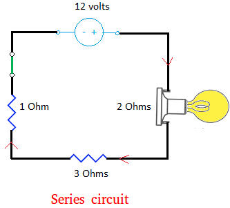
voltage change in the circuit. Below is an example of a series circuit with 5 electrical components, excluding wires.
The circuit has 1 switch (green), 1 voltage source of 12 volts, and 3
resistors. Notice that the light bulb is also a resistor!
A circuit is in series if the current has a single pathway.
Simply put, the current cannot "make choices" as to where it would go in a series connection. If the current can either go this way or that way, then the circuit is not in series. A circuit that can "make choices" is a parallel connection.

Look carefully at the circuit above and you
will see that the current has to go through the path it is in. This fact
leads us to Rule #1.
Rule #1: In series circuits, the current passing through each electrical device is the same.
Let I1 be the current going through the 1 Ohm resistor.
Let I2 be the current going through the device with 2 Ohms resistor.
Let I3 be the current going through the 3 Ohms resistor.
Then, I = I1 = I2 = I3
This series circuit has 3 resistors. Recall that a load resistor or simply resistor is a device
that resists the flow of current. Does it make sense to you that the
current will be resisted by all 3 resistors? It will indeed!
Rule #2: In series circuits, the total resistance, also called the equivalent resistance of the circuit, is found by adding the individual resistance of all resistors in the circuit.
For example, to find the total resistance for our circuit above, just add 1, 2, and 3.
Let R1 = 1 Ohms, R2 = 2 Ohms, and R3 = 3 Ohms be the resistance in the circuit.
Total resistance = 1 + 2 + 3 = 6 Ohms.
We can now use Ohm's law to find the intensity of the current flowing through the circuit.
I = 2 amperes
Whenever the current goes through a device, a voltage drop or potential
difference occurs because of the resistor in that device. It simply
means that the voltage in that device will not be the same as the
voltage source.
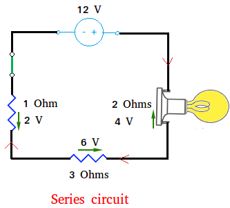
Voltageacross device with 2 Ohms resistor = R × I = 2 × 2 = 4 volts
Voltageacross 3 Ohms resistor = R × I = 3 × 2 = 6 volts
From this, there is an important observation we need to make.
Notice that 12 volts = 2 + 4 + 6
Rule #3: In series circuit, the voltage supplied by the source, also called total voltage, is the sum of the individual voltage drop at each device.
Let v1 be the voltage across the 1 Ohm resistor.
Let v2 be the voltage across the device with 2 Ohms resistor.
Let v3 be the voltage across the 3 Ohms resistor.
Then, V = v1 + v2 + v3
Series circuit rules generalization
The series circuit rules can be summarized and generalized as follow:
Let I be the current going through the circuitLet I1, I2,..., In be the current going through other devices.
Then, I = I1 = I2 = ... = In
Let R1, R2,..., Rn be the resistance of devices in the circuit.
Then, R = R1 + R2 + ... + Rn
Let V be the voltage at the source
Let v1,v2,...,vn be the voltage drop across other devices.
Then, V = v1 + v2 +...+ vn
Gustav Kirchhoff’s voltage law

Using the same circuit again, we can make the following important observation:
12 volts = 2 volts + 4 volts + 6 volts
12 volts - 2 volts - 4 volts - 6 volts = 0
12 volts + -2 volts + -4 volts + -6 volts = 0
The sum of all 4 voltages around the loop is equal to zero.
In general, this is known as Kirchhoff’s voltage law and it states that the algebraic sum of all voltages around a loop is equal to zero.
Σv = 0
The meaning of the negative sign in front of -2 volts for instance is voltage drop. Furthermore, the direction of the voltage drop shown with the green arrow is opposite to the direction of the current.
Series circuit rules quiz
Take the series circuit quiz below to see how well you understand series
circuit. After completing this quiz with 100% accuracy, you will know
exactly how the current, the voltage, and the resistors behave in a
series circuit. You will not need to use a paper and pencil to complete
this quiz.
First, read the lesson about series circuit and then take this quiz.
Objective of the series circuit quiz:
- Know how the current behaves in a series circuit
- Know how the voltage behaves in a series circuit
- Know how the resistor behaves in a series circuit
- Know how to apply Ohm's law to find the current going through the circuit.
- Know what a voltage drop is.
- Find the current in the circuit
|
Test your knowledge with the quiz below: |